In general, thermal effects are the cause of 40 percent of the total error of a machine tool

Tim Knobloch about the Thermal effects in mechatronic systems training
Making ultra-precise milling machines even more precise is how one could describe Tim Knobloch’s job. Thermal effects play an increasing role in his field. He therefore attended the ‘Thermal effects in mechatronic systems‘ training.

Kern Microtechnik GmbH has been building ultra-precise CNC machines in the southern German state of Bavaria for more than sixty years. They do this with over 250 people, spread all over the world. For the German specialist, precision is more important than ever.

Kern supplies precision production at the top market segment of accuracy. Customers are producers in the watch industry, medical technology and semiconductor mechanical engineering.

Within the Kern Micro platform, we develop different machine versions. “We use hydrostatic bearings, with very low friction,” says Tim Knobloch, precision engineer at Kern Microtechnik. Where you usually see streaks on milled parts from standard CNC machines, the surfaces of workpieces from Kern’s machines have mirror-quality. The machines can mill parts up to roughly 50 kilograms with diameters of up to 350 millimeters. ‘Usual is 200 millimeters.’

Precision engineer

Knobloch is a precision engineer, but his main focus is systems engineering for precision. ‘I look at quality challenges. Our machines have to meet very high standards. That’s why we test intensively to detect and correct problems.’

That makes Knobloch’s job very broad. ‘At Kern, my precision engineering colleagues and I work more or less as project engineers. We are working in many fields like mechanical construction, software programming, experimental testing along the problem solving process.’

We look at a problem or issue from many angles, looking at the whole process. We do design and modeling first, then prototyping and testing, and then continue with to the actual development and integration into the platform. Mechanical, software and electrical engineers work side-by-side in this process.’

Training participant Tim Knobloch from Kern Microtechnik
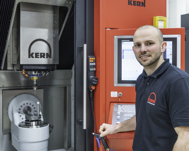
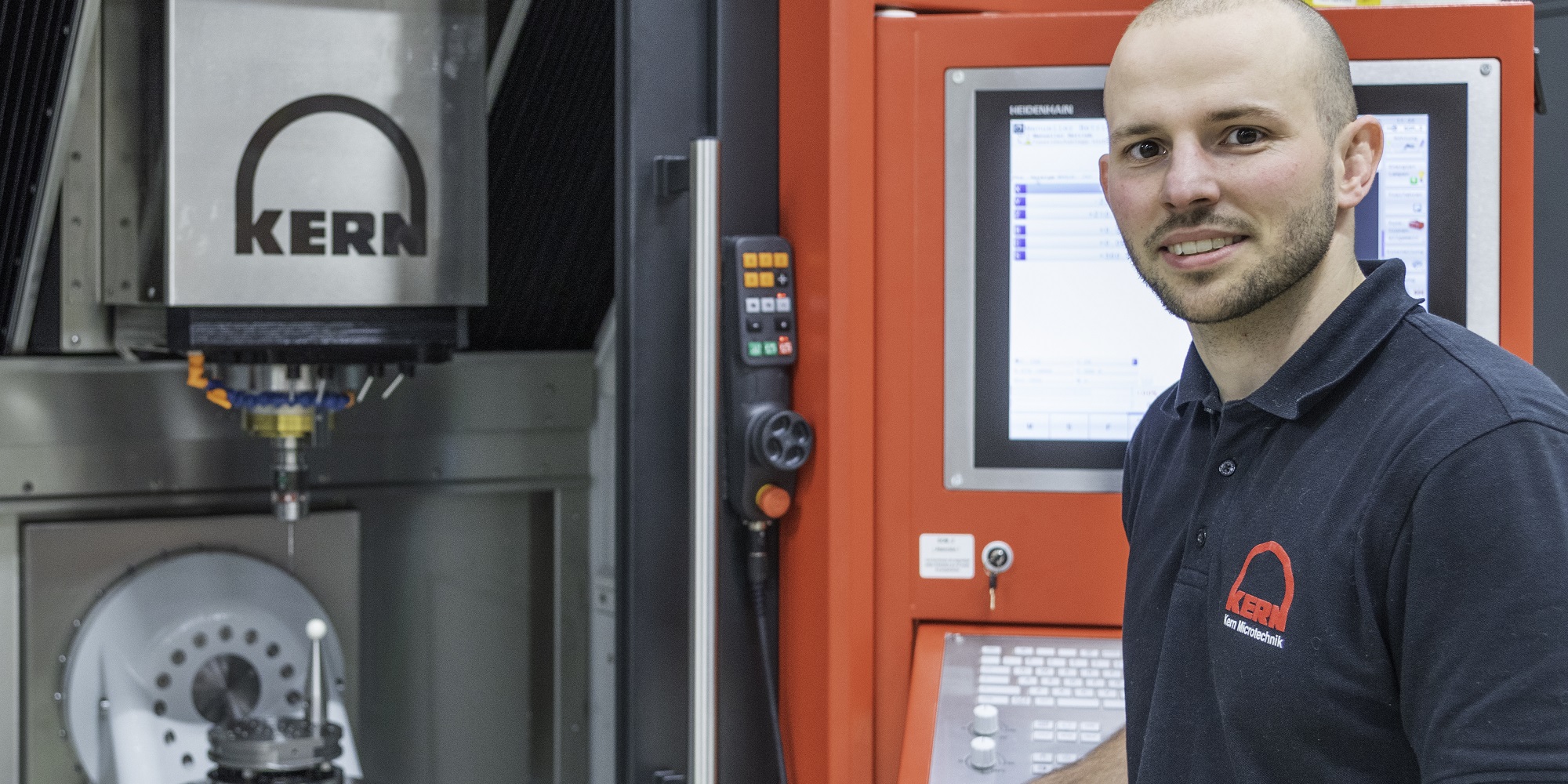
Tim Knobloch of Kern Microtechnik works on milling machines that machine ultra-precise, whether they are in a clean room or in an unconditioned space. Photo Kern Microtechnik.

Thermal effects

Along with a colleague, Knobloch took the training course Thermal effects in mechatronic systems at High Tech Institute. That decision resulted from Kern’s goal of making it’s machines as precise as possible while minimizing errors. Nowadays, in general, thermal effects are the cause of about 40 percent of the total error of a general machine tool like a milling machine. I am talking about the total error of the machine tool, the geometric error on the workpiece after processing like milling or grinding. That’s really substantial. Every part can be affected by it. Because we at Kern put a lot of effort in the cooling of the machine, we may be better than 40 percent, although, I can’t give you an exact number.
Sometimes a machine from Kern ends up in a university, where it is used in a clean room with good climate control. But with other customers, such a machine can end up in a somewhat more uncontrolled production environment, with strong temperature variations. To still be able to machine precisely in those unpredictable environments, Kern builds speciallized parts for it’s machines, such as heat exchangers. Here, too, knowledge of thermal effects comes in handy. ‘That’s an important subject, because we use oil under high pressure. Such an exchanger is a part you can’t just buy from another company. Among other things, I was interested to see how you can model a heat exchanger without very long compute times.’

Netherlands leads the way

Germany, of course, is known as a country of mechanical engineering. But according to Knobloch, it is no coincidence that he did this training in the Netherlands, and not in his home country. ‘The Netherlands and the United Kingdom are further ahead than Germany in precision engineering. There are smaller modules or courses you can take at universities, but you can’t really learn it properly. My boss, the head of development at Kern, happened to work at Philips before. That’s how we knew about the existence of High Tech Institute.’

Efficient model

An important aspect of the training was the mapping of thermal effects and thermal modeling methods. In the training, participants learn to use so called lumped mass modeling to gain a good understanding. This method roughly allows you to model the essence through masses – in thermal context: the thermal capacities – and the heat exchange between the different parts. In the conceptual phase, this is a very effective tool, because if you don’t yet have a fully worked-out CAD model with all the details, you can’t create a detailed FEM model at all.

Knobloch: ‘We learned to model much more efficiently with this than with finite element methods. FEM calculations take a long time. I myself always spend a lot of time with them. Lump mass modeling is often much more efficient. Simply put, the advantage is that you have to think better about your system, about how to reduce it to its essence. So you get a better understanding of your model, and whether there’s something wrong with it.’

''I learned a lot of new things about heat exchange and how to model it.''

Knobloch was familiar with Lumped mass modeling.  It is one of the basic modeling techniques he learned at university. The Lumped capacity modeling in the course however, was tailored to his level and interest. ‘I had read about it, but never actually tried it. I also was never able to take a course around heat exchange in college. So that part of the subject was new to me. It wasn’t difficult for me, because I have basic thermodynamic knowledge. But I learned a lot of new things about heat exchange and how to model it.

Knobloch says knowledge of thermal effects also helps Kern with his most essential work. Much of the effort in manufacturing at the company is in making a machine fingerprint after assembly. Says Knobloch, “We characterize the machine, and compensate for the errors that are still in it.”

Not crazy

Knobloch on the trainers: ‘I advised my colleagues to participate in the training as well. The trainers were very good. They didn’t just teach, but started from their own practical experiences. They connected those insights to your own background and situation. They not only explained, but also showed how to do it. It was like talking to a colleague, not a professor at the university.’

Knobloch also enjoyed the interaction with other trainees. ‘With that, it became clear to me that my problems were also at play in many other companies. For example, there were people from ASML and Zeiss present. They, of course, specialize in semiconductors or optics, but it was very interesting to see what problems they were running into.’ He laughs: ‘Sometimes our problems seemed small compared to theirs.’

''It's reassuring to know that others are struggling with the same problems.''

A bond was also formed. ‘When we talk to our suppliers and have specific requirements for parts, sometimes they declare us crazy. Sometimes they say it’s just not available. At the training I heard from other participants that this happens to them regularly as well. It was nice to be confirmed that we at Kern are not crazy, ha ha. It’s reassuring to know that others are struggling with the same problems.’

This article is written by Tom Cassauwers, tech editor for High-Tech Systems.

Recommendation by former participants

By the end of the training participants are asked to fill out an evaluation form. To the question: 'Would you recommend this training to others?' they responded with a 8.7 out of 10.

Working efficiently with a standardized language

With new developments, engineers often apply proven designs, with or without minor modifications. So why do they still fail to deliver solutions that customers demand? Usually, communication is the major stumbling block. High Tech Institute trainer Eric Burgers explains how SysML helps to successfully communicate design ideas for complex systems. Eric Burgers teaches the course Introduction to SysML and System modelling with SysML.

In an ideal situation, a project starts with perfect requirements: unambiguous, specific and precise, and just enough to describe the problem to be solved, with sufficient room for creativity and innovation. The designs meeting these requirements are complete, specify decomposition, behavior and collaboration completely and are 100 percent consistent and testable in all respects. Ultimately, a system is delivered according to the requirements and fulfilling its intended use.

In a nightmare version, a project departs from inconsistent or contradictory requirements, containing phrases like “the system will facilitate …” or “contribute to …”. The system boundary is difficult to define. The whole is decomposed into vague components, such as (categories of) devices or even arbitrary groups of “things.” Desired behavior, if specified, appears to be separate from the design or is factually incomplete, leaving much room for interpretation. In the ultimate nightmare version of a project, a system is built that’s not based on the actual design. Defects are repaired by piling note upon note, making the design file an absolute mess. Only when everything is read in the correct order can the actual design be derived.

                    Eric Burgers Boehm

Boehm’s second law of engineering: during a software project, costs to find and fix bugs get higher as time goes by.

Most projects aren’t complete nightmares but neither are they ideal. Created designs don’t always meet all requirements and may contain inconsistencies, omissions or other defects. These defects are a potential source of failure costs: defects introduced during requirements analysis or design become more expensive to fix the later they’re resolved. All while they could have been prevented.

This raises a point of conflict: designs are meant to mitigate the risk of building wrong or faulty systems, yet projects very often create designs that don’t reflect the customer’s requirements, thus defeating the whole purpose of a design. Why is this and what can be done about it?

''Only when everything is read in the correct order can the actual design be derived.''

Bottom-up approach

Projects come in all shapes and sizes and solve simple to challenging problems. Relatively simple, small projects aren’t too difficult to complete. The risk of failure increases as a project becomes more complex. The complexity of a project is related to the complexity (in terms of size or difficulty) of the product being made and the size of the organization making it.

Large(er) projects are often organized into discipline-specific development groups. These groups do discuss their interfaces with each other, but there’s usually no overarching approach to describing how to integrate all the components into one working whole. Sometimes it even seems that interfaces are created ad hoc.

This has all the traits of a bottom-up approach, where discipline-specific parts are first designed and produced and then assembled in the hopes of getting a working product. Such an approach may work for less complicated projects where engineers can understand the entire product with all its details. When parts can affect each other through their behavior or properties, however, it can be difficult to assess how the whole will behave, especially if the building blocks come from different disciplines.

Eric Burgers complexity

The risks of increasing complexity

Drawings

One way to deal with large, complex projects is to create extensive documentation to disseminate design ideas to all engineers involved. In technical fields such as mechanical engineering, software engineering, industrial automation and civil engineering, there are often standardized ways to do this. In practice, documentation is supplemented by drawings made in popular tools such as Powerpoint or Visio (Windows) or Omnigraffle (Mac OS). In addition, Excel is used to exchange large amounts of information.

In multidisciplinary projects, the use of supplementary drawings and other project-specific tools increases to bridge the gap between the disciplines. In principle, there’s nothing wrong with this; the transfer of design ideas and information between disciplines is badly needed. Without bridging the interdisciplinary gaps, a project will encounter serious integration problems. However, “project-specific” also means repeatedly inventing the wheel, especially when the work is done by consortia that change from project to project.

Another problem with these drawings is that there’s no general agreement on what they should represent. Moreover, there’s no guarantee that they’re complete and consistent. As a result, there’s a real risk that the drawings, although clear to the author, may be misinterpreted by readers, which in turn leads to defects in the product that aren’t discovered until later stages of the project.

Very often this way of working and the associated integration problems are simply accepted. As the project approaches the completion date, the problems are resolved through rework or patching, or they’re simply left in the project as “future work.” An alternative approach is to standardize the communication of design ideas on a project or even company basis. This has the disadvantage that the conventions are ‘local’ to the project being undertaken – each participant will have to learn them.

It makes more sense to adopt an industry standard, including supporting tools. Then the conventions only need to be learned once to be applied many times, regardless of the project or organization. All the better if the standard allows documents and drawings to be replaced by a single source of truth that’s always up-to-date.

Modeling language

The complexity of projects, or technology in general, is only increasing. Think of the difference between the first phones and today’s smartphones. Or compare the first cars with the vehicles seen on the road today. While the main function has remained the same (communicating, driving), today’s systems are increasingly integrated into a larger whole to provide users with additional services that can’t be provided by the systems themselves. This trend has been identified and described in many sources, including the vision documents of Incose – Vision 2025 and more recently Vision 2035.

To cope with the increasing degree of integration, Incose is promoting the transition to model-based systems engineering (MBSE). This involves using models to design and verify complex systems. One of the first steps toward MBSE is the adoption of a language suitable for building such models. SysML is one such language.

''The complexity of projects, or technology in general, is only increasing.''

Eric Burgers SysML

SysML allows the representation of different types of systems and their behavior, as well as their interactions with the environment.

The Systems Modeling Language (SysML) is a general-purpose modeling language designed to help engineers develop and document complex systems with a large number of components. The language is widely used in industries such as aerospace, automotive, infrastructure and defense. The graphical notation provided allows the representation of different types of systems and their behavior, as well as their interactions with the environment. This enables engineers to effectively and efficiently communicate their ideas and ensure that all those involved in the development process have the same understanding of the product to be built. Because the language isn’t discipline specific, systems can be described at an overarching level.

The four pillars of SysML

  1. Structure: a system can be decomposed into smaller parts, which have interfaces with each other.
  2. Behavior: three types of behavior – flow-based, event-based and message-based – can be specified and related to one another.
  3. Requirements: system requirements and their tests can be defined.
  4. Parametrics: once described, a system can also be simulated.
                    Eric Burgers SysML pillars

Increased precision

When using SysML, the first thing you’ll notice is that the designs are more precise and thus require extra work to complete. However, that precision also ensures that everyone involved can interpret the designs in the same way as the author and that defects and omissions are much easier to identify and prevent. Because it’s almost impossible to create an inconsistent design, failure costs are avoided. If these costs exceed the initial investment, there’s a business case for using SysML.

Implementing SysML can come across as a daunting task. At first glance, it can seem like a considerable challenge to mold an entire complex system into a model suitable for analysis and simulation. In practice, the transition is often incremental and organizations gradually apply SysML more and more to describe designs. Slowly but surely, documents are either being replaced by models or become views on the model, until at the higher levels of maturity, there are no documents at all because all information is encapsulated in models.

As SysML is a comprehensive language, it takes time to master all the details. Proper training will speed up adoption considerably. Engineers will certainly also have to get used to the increased precision with which designs are created from the start. Once successfully adopted, SysML will improve design communication and quality.

For specifications with a lot of geometric information, as often created in civil engineering, SysML is less effective. The language lends itself particularly well to cyber-physical, software-intensive systems. A good example is an infrastructure project in Amsterdam-Zuid, where the designs were created by the supplier and reviewed by the acquiring party. Here, the use of SysML resulted in a significant increase in development speed, with the number of defects found being significantly lower than average. Also elsewhere, SysML is proving that it can prevent nightmares and bring projects closer to the ideal.

This article is written by Nieke Roos, tech editor for Bits&Chips.

Recommendation by former participants

By the end of the training participants are asked to fill out an evaluation form. To the question: 'Would you recommend this training to others?' they responded with a 7.6 out of 10.