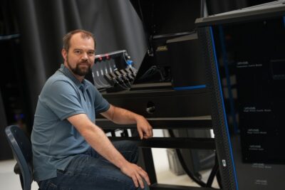
‘Without statistics you are unlikely to find your best performance and realise consistency’

It’s easier than ever to do complex calculations and design simulations. Yet in the end it all boils down to how a design will work out of the lab, in a real product, in a real environment, according to Wendy Luiten. That’s why she’s teaching a new course called Applied statistics for R&D at High Tech Institute. ‘Statistics are often under applied, which is a pity because it can really contribute to success.’

When Wendy Luiten was taught to program, she used punch-cards that were fed into giant computers. Nowadays she can do the most complex calculations and design simulations with the press of a button on her laptop.

During Luiten’s career she witnessed an unprecedented increase in processing power. Graduating in 1984 from the University of Twente, she embarked on a distinguished career as a thermal expert and as a Six Sigma Master Black Belt at Philips. Today she works as a consultant.

That deep experience gave her a better view of statistics and computing than most engineers. New software offers great opportunities for making design simulations and Digital Twins. But the apparent ease of these new methods makes it easy to forget that a simulation is not reality. A simulation model needs to be validated to ensure that it represent reality to a sufficient degree. In addition, simulations describe an ideal world, without random variation. In the real world, random variation can make a product unreliable and disappointing to end customers.

‘Some people do not repeat, but go on a single measurement’, she says. ‘Based on that, they decide whether the design is good or not. That’s risky. You do not know how good the measurement is, you have no idea about the measurement error, you do not know how representative the prototype is, you do not know how representative the use case is.’

“Applied statistics is like driving a car, you do not need to know the working of the engine to go from A to B,” Wendy Luiten

People tend to be very optimistic about their measurement error. ‘I saw cases where people thought their measurement error was in the tenths of a degree, but a repeat measurement showed a difference of 10 degrees C. In the thermal world, that is a huge difference. So, if your repeat measurement shows such a big difference, you really cannot be sure on how well the product performs and you need to dig deeper as to the root cause for this difference.’

This is why Luiten starts her new training on Applied statistics for R&D at the High-Tech Institute with measurement statistics. In this course she will dig into key statistics skills that have shown their worth in her 30+ years of industry R&D experience. ‘First, you need to see how good your measurement is’, she explains. Then you need to be able to estimate the sample size, the number of measurements that you need to show a certain effect with sufficient probability. Once you can measure output performance accurately and with sufficient precision, you can explore different design configurations and choose the best configuration. Finally, you investigate the output mean and variation, which is ultimately how you achieve a successful design.’

''In the real world, we do not have unlimited resources, you need to prioritize.''

Random measurement error

Luiten notes that engineers often are already aware of the systematic measurement error. ‘Systematic errors are a well-known field’, she says. ‘You can measure a golden sample and correct the results, that is a de facto calibration of your measurement. Well known, and part of many lab courses taught in higher education’.

Most people, however, don’t consider the random error or blindly use a default value of 1, 5 or 10%. But in reality, the random error depends on the measurement instrument and also on who is performing the measurements. The statistical method to find out the random error is not usually part of a lab course, so this is less common. But the first time such a test is done, the results are often surprising.’

Luiten mentions some cases she dealt with herself. ‘I have seen cases where people were confident that they had almost no random error because they had a very expensive automated measurement machine. But it turned out that the operators were making the samples in a different manner, and that caused a large random error. In another case different development labs were all claiming a 5% measurement error – but when they measured the same devices in a round robin test, there was a difference of a factor 2, because of differences in the measurement set up that were thought to be irrelevant. I have seen that apparent fluctuations in product quality could be linked to the operator performing the measurements. In all cases people were absolutely convinced that they had a negligible random error in the measurements, and these results were totally unexpected. But you only know your random error and the cause of the random error if you do the statistical test for it.’

“Which design is better? Design C is preferred – Even though B has a higher average performance, C has the lowest failure rate because it performs consistently, ” Wendy Luiten

Measurement repeats

The random measurement error is especially important when it comes to so called statistical power – the probability of measuring a certain effect if it is present. If the effect you want to measure is about the same size as your measurement error, and you repeat your measurement twice, the probability of proving that effect is below 10%. So, if a design change gives you a 5C lower temperature, and your random measurement error is 5C, you will see that in 1 out of 10 measurements, and on average 9 out of 10 times the results are unconclusive, even if you do the measurement in duplicate. If you want to improve the power, you either need to lower the measurement error, or do more repeats. Sometimes people see repeat measurements as a waste of effort, but Luiten does not agree with that. ‘The true waste is to run underpowered experiments, going through all the effort of setting up and executing an experiment – and then finding out that the result is inconclusive.’

Testing different design options

Besides measurement errors and sample size estimation, a key element of the course will be testing of different designs. You can do that in hardware, but that might not be the most effective option. ‘Nowadays you can do a lot by virtual testing’, says Luiten. ‘Before you even make a prototype, you can experiment with your designs using computer simulations. Inputs can range from materials and dimensions to power and control software. You can, for example, model the impact of different materials or dimensions, or the use of a different mechanical layout, or different settings in a control algorithm. In every product there are lots of choices to be made, both on the level of the architecture and in the implementation. Finding out what inputs are the most important, and how these inputs determine your performance is key because you don’t want to realise in a later stage that an earlier decision was wrong. A Trial-and-error approach is often too expensive in time and money.’ The statistical approach is to set up a set of experiments in a special way, varying multiple inputs at the same time and not comparing single experiments but groups of experiments to tease out the effect of a single input or interactions between two inputs. This is a very powerful approach, especially in combination with computer simulations, but for a small number of inputs you can also do this in hardware. If you do the experiments in hardware, the calculated sample size from the earlier stages determines the number of repeats for the different experiments. If the experiments executed virtually, through computer simulations, the sample size is used for the validation experiments for the computer model.

''In innovation, you need to focus on the vital few parameters that really impact your design.''

Making the best choice

The next tool in the statistics toolbelt is optimization or making the best choice. Once you have found out what are the key input parameters and how they relate to the performance, you can make a data driven decision of what design configuration suits your purpose the best. Often there are multiple outputs to consider, for instance if you want high strength but at the same time low weight. Multiple Response Optimization is a well-known tool for this.

The effect of input variation

‘Once you know the impact of an input, it’s also important to look at its variation, and in turn what kind of variation it causes in the performance’, Luiten continues. ‘ This is also something that people are less familiar with but once you know how to do it this is not that difficult, and it is important. For a design to be a success, it’s not just peak performance that matters, but also that you consistently achieve that performance. Using statistical simulations tool, you can make a statistical model to link the mean and variation of your output to the statistical distribution of your inputs.

Sometimes people say that this is no use because they do not know the variation in the inputs. But if an input is important, not considering its variation is risky in terms of consistent product quality. If the statistical model shows that the input is important, you have good cause to discuss with the supplier what the distribution is and how much variation it has. This is common in automotive industry, in fact they have formal procedures in place defining exact requirements not only on the mean but also on the standard deviation of components and sub-assemblies.

Navigate the solution space

Statistical methods, in other words, help to navigate all possible configurations that together form the solution space. Luiten says “You don’t just reach your optimum performance by accident. If you have two inputs that can be high or low, that leaves four possibilities. But if you are designing something with five inputs, that leaves 32 possible configurations. And many modern-day designs have more inputs than that. And that is without even taking all the possible tolerances into account, and all different user cases. Without a structural, statistics-based approach the probability of finding optimum consistent performance is small.’

Driving cars

The components of Luiten’s course are closely interrelated, it is a chain of tools. ‘If you, for example, want to validate results, then you also need measurement statistics to tell you what your random error is. This in turn shows how large your sample needs to be, so that the experimental set up is correct. Only then can you decide whether you can trust your validation’, says Luiten.

''The aim of the training is not to become a statistical expert, but to be able to reach your goal with statistics.''

Luiten takes a practical approach. For her, statistics is an applied skill, a means to an end. ‘Statistics in university is taught in a very theoretical way’, says Luiten. ‘I saw this in my own studies, and I saw it when my children were studying. It’s taught in a way that had limited practical use in my line of work. I compare it to driving a car: You do not need to know exactly how the engine works in order to drive from A to B. The aim of the training is not to become a statistical expert, but to be able to reach your goal with statistics.’ And mathematical tools like excel and statistics software makes application much more accessible nowadays.

Master Black belt Six Sigma

Luiten is a Master Black Belt in Design for Six Sigma, and her career has supplied her with a deep understanding and rich experience in the application of statistics in innovation processes. ‘In my experience, many engineers learn by doing, and that makes sense. You cannot learn swimming by watching the swimming Olympics, you need to get into the water yourself, even if it is only to learn how to float. So, we have practice exercises, either in excel or in a dedicated statistics tool.’ Statistics for Luiten is a general-purpose tool, and familiarity with the techniques and tools she mentions in her course is key for engineers working in a variety of fields from technical experts to designers and team leads to system architects.

‘This is a general course for people in innovation, that develop products and do research. If you measure output in continuous numerical parameters, it doesn’t matter what technical field you are in. I used these techniques in thermal applications, but any field can use them, from mechanics and electronics to optics and even software, this is mathematics. You can decide for yourself what you’ll use it for. ‘

This article is written by Tom Cassauwers, freelancer for High-Tech Systems.

“It’s a competitive advantage if you can take part in the discussions about the application at a high level.”

To better understand his customers’ technology and applications, Ralf Noijen, systems engineer at AAE, took the Applied Optics course at the High Tech Institute. “We like to take part in the discussions at a high level,” he says.

In Helmond, AAE produces the C-Trap for Amsterdam-based LUMICKS. With this instrument, researchers can investigate, among other things, the binding of proteins to DNA strands. Understanding this molecular interaction is important to clarify the mechanisms of specific diseases.

For that research, it is necessary to manipulate the DNA strands. To do so, they are connected at the ends to small polystyrene beads. That combination is then placed in a liquid in contact with labelled specific proteins. The C-Trap allows researchers to study DNA strands with bound proteins using optical techniques.

The instrument is able to manipulate the beads with laser beams. “You can think of it as optical tweezers,” Noijen explains. “The laser beams catch small beads of polystyrene flowing through a glass channel. Between two beads is a single strand of DNA containing proteins labelled with fluorescent substances. By pulling two beads apart with optical tweezers, the stiffness of the DNA strand can be measured and thus the influence of the bound proteins. Sub-pico-Newton forces can be measured with this system.”

The instrument mainly serves to research diseases such as cancer. “The main customers of these machines are universities and research institutes,” said Noijen.


Ralf Noijen: “Theoretical parts of the course were balanced with a healthy dose of experimentation.”

Small microscope with flowcell

Another project AAE is building for LUMICKS is the z-Movi platform. “That is basically a small microscope with a flowcell in which tumour cells can be grown,” says Noijen. “The microscope is used to study the binding between cancer cells and immune cells. Those cancer cells are brought into contact with the drug of a specific immunotherapy in the flowcell. On top of this flowcell, a piezo element is attached. The piezo element vibrates the fluid in the channel and creates a standing acoustic wave. The immune cells are attracted to the node in the standing wave. By increasing the amplitude, the attached immune cells release at some point, which tells us something about the strength of the binding. The Cell Avidity platform measures the moment of release optically. This gives us information about the binding and thus the effectiveness of immunotherapy.”

''Throughout the course, we learned about the latest updates in all the areas covered. We were taught by real experts.''

Understanding sensitivities

The great importance of optical phenomena prompted Noijen to take the Applied Optics course at the High Tech Institute, mainly as a basis for working with customers. Noijen: “At AAE, we focus on manufacturability, testability and assembly. But we like to think along in the development process so that we can take care of all aspects. Over the years, we already built up a lot of application knowledge and we oversee more and more parts of development. That is precisely why a course like this one comes in handy. Optics is very important in the LUMICKS systems. The better we understand their sensitivities, the better we can assess whether our proposals will work.” Noijen already had experience with training courses from the High Tech Institute. “When I saw the Applied Optics course description, I thought: ‘hey that fits in nicely with the platforms we build for LUMICKS.’”

Carving out time

The course was intensive, notes Noijen, totalling 13 half-day sessions over six months. In between, he did five homework assignments. That was tough, but Noijen is nevertheless positive about the experience. “I just found it very interesting, so I didn’t have much trouble taking the time out for it,” he laughs. “You have to schedule it, of course, because life is busy.”

On the structure and content: “It started with the basics of light, what is light? From there we went to modelling and when you can use it. Which aspects are important? For example, when can you use ray tracing? I liked the build-up from basics to applications. Then lighting and sensors were also covered. The last sessions went deeper into ASML’s lithography. I found that very insightful. I worked at ASML so the subject matter was not entirely new to me, but still there were many things that I saw for the first time. Throughout the course, we learned about the latest updates in all the areas covered. We were taught by real experts.”

The theoretical parts of the course were balanced with a healthy dose of experimentation. “It goes deep into theory, but then you start experimenting. When you experience how everything really works, the theory sticks better. You learn more easily when you’ve had something in your hands. That was the uniqueness of the course.”

''If I had done this course earlier, I would have been better able to spar with the opticians in previous projects''

Discussions

For Noijen, the optics course was especially important to build a better connection with his clients. Deeper technical knowledge allows him to better engage with experts and companies. “I think we can now participate at a higher level,” he states. “That’s really nice. You learn to speak the same language about a machine. If I had done this course earlier, I would have been better able to spar with the opticians in previous projects. This also helps AAE by the way. Our primary proposition, especially for start-ups, is that we build their machines. But on top of that, you still have a competitive advantage if you can talk about the application at a high level. If you can show that you understand the sensitivities, that builds confidence.”

This article is written by Tom Cassauwers, freelancer for High-Tech Systems.

Recommendation by former participants

By the end of the training participants are asked to fill out an evaluation form. To the question: 'Would you recommend this training to others?' they responded with a 8.6 out of 10.

Bearings contribute to accuracy and system behavior

When designing a mechatronic system, the actuation often receives the most attention. But the bearing is just as decisive for the accuracy and the system behavior. Hans van de Rijdt and Marc Vermeulen are therefore developing a new training for Mechatronics Academy that is scheduled at High Tech Institute in March 2024: ‘Bearing principles for precision motion’.

There is a wide choice in machine building when it comes to bearings, from sliding, roller and air bearings to hydraulic, elastic and magnetic bearings. Choice stress is therefore lurking. However, that has not prevented bearing technology from becoming somewhat neglected in the high-tech world in recent decades.

Marc Vermeulen, working as a principal mechanical system architect at ASML, does have an explanation for this. “In mechatronics we often talk about the actuated direction, in which you have to achieve a certain accuracy with a drive and a measuring system.”

However, the direction perpendicular to the driven direction is equally important. “Then you’re talking about the degrees of freedom that you don’t actuate. So, you have to constrain these and how do you do that? Because that ultimately determines the accuracy and the entire system behavior to a large extent. The bearings are indeed important for that.”

At least three errors

In his work as an independent consultant in the high-tech industry Hans van de Rijdt regularly encounters that certain bearing principles are overlooked or that pitfalls are not avoided. Together with Vermeulen, he developed the Bearing Solutions training course that will soon start at High Tech Institute. Van de Rijdt: “It happened recently during a review of a large project, on which 140 people worked. Then you would expect that there are enough of them who know something about bearings. Still, I saw at least three errors in the application of bearings.”

It was a design in which the bearing makes a very small angular movement. “That bearing can jam because the lubricant is not distributed properly. That had not been taken into account. Also, an incorrect ball cage had been used, so that the required number of strokes would not be achieved. Bearing suppliers often don’t tell you that sort of thing. If you call, you will get the salesperson who does not know either and it is very difficult to get in touch with the engineer.”

Hans van de Rijdt (left) and Marc Vermeulen (right).

From performance and service life to noise pollution and delivery time

Many factors play a role in the choice of a certain bearing type. In the first place the performance – think of accuracy, speed and acceleration – and the service life, which can be negatively affected by friction and wear. An air bearing scores high on both, but less on costs. For example, an air supply must be integrated into the system design.

Depending on the application, other factors may come into play. A good example is patient welfare. This is the case with CT scanners, for example, where an X-ray tube provided with bearings rotates in a circular gantry around the patient. At Philips, such a scanner was always equipped with a roller bearing, Van de Rijdt recalls, but at a certain point they switched to a large air bearing. “That was for the sake of performance, but above all to reduce noise pollution from the bearing.”

In coarse applications, the choice of bearing can also be crucial. Van de Rijdt talks about a large offshore crane with a ring bearing of 8 meters in diameter. “The lead time for making that large ring bearing was one and a half years, because it was of course not in stock at the factory. That’s why they looked at a sliding bearing as an alternative, which would be much more favorable in terms of lead time. I then made a complete study of it. In the end, that alternative was dropped because the stick-slip behavior of the sliding bearing with such a large diameter had too much of an impact on the operation by the crane driver.”

''For some applications, the performance of ball bearings is sufficient and then their application is more cost-effective.''

Ingrained patterns and new competences

In addition to rational substantiation, the choice of bearings often also involves ingrained patterns, says Vermeulen. Placement machines, for example, use roller bearings and not air bearings for cost reasons. Roller bearings, on the other hand, are not used in lithography machines, because lubrication and wear could cause contamination. “Not appropriate in a semicon factory; that’s is a kind of dogma for many manufacturers.” However, the question of whether air bearings can still be replaced with roller bearings for cost reasons comes up regularly.

Van de Rijdt recently was faced with it again. “I could just refer to my report from twelve years ago. For some applications, the performance of ball bearings is sufficient and then their application is more cost-effective. I just tested what people were afraid of. You can neatly control the contamination by ensuring that the bearings are in a downflow under the wafer.”

Things are moving in the meantime, Vermeulen sees at ASML. “All kinds of tests with lubricants and measurements of stiffness and friction are now underway for roller bearings, for example. Of course, we already had the competences for air bearings, magnetic bearings and also elastic bearings (leafspring guides are a popular bearing solution for stages with short strokes, because they are accurate, backlash-free and frictionless, ed.). So now a certain competence is also being built up for roller bearings.”

Avoid overdimensioning

That broad range of competences is important, says Vermeulen. “Leafspring guides have become somewhat self-evident for us. You can make them in one piece, monolithic, with wire EDM. At a certain point you just cannot stop adding complexity and costs. ‘Better safe than sorry’ then becomes the motto, ‘let’s do it this way, then we’ll know for sure it’s right’. But you also have to consider the cost aspect; this is becoming increasingly important.”

Van de Rijdt agrees: “If something has to be nanometer accurate, then monolithic and wire EDM will do the job. As soon as you get out of that range and just talk about micrometers, it doesn’t have to be monolithic. For example, I have designed focus modules for different applications, with exactly the same specification. There was a factor of ten price difference, purely due to the chosen design for the guide.” Vermeulen: “So it starts with the assumptions on which you design a device. The same applies to the bearings. Overdimensioning and preventing that should be a common thread here.” In this way, more attention to bearings can lead to less complexity and costs.

Solutions and applications

The new training will be called Bearing principles for precision motion. That’s a conscious choice, says Hans van de Rijdt. “It’s about solutions for concrete bearing problems, about applications of different types of bearings. We do not dive very deeply into, for example, the tribological aspects, but it’s much more about when you can use which type and what you have to take into account. The best thing is to tell about it from your own experience.”

Insight into how a bearing works will be presented, says Marc Vermeulen. “Many people don’t know, for example, that you can pull an air bearing if you pretension it. So, for example, the fundameltal question of what gives a bearing stiffness will be addressed. But we are indeed not going to discuss the differential equations that describe the motions in a bearing.”

''We want to provide the designer and the architect with insight into bearing selection and applications.''

Because that’s usually not where the problem lies in practice, adds Van de Rijdt. “Many people are analytically very strong, but they must have a design to make calculations about. I often notice, not only for bearings but across the entire system scope, that designers and architects have difficulty putting the first lines of a design on paper. If you want to make an initial estimate for a bearing to determine whether it can achieve the required performance and service life, you must first set up a design for it. Going through those iterations is something I want to help people with.”

The training is aimed at designers and architects who regularly have to select a bearing type in their designs. They then have to make a trade-off and optimize the application of the chosen bearing. This is also where control engineering comes into play, for example with magnetic bearings. Think of the ‘flying carpets’ in the ASML machines that have to continuously position a wafer at lightning speed. Vermeulen “They do indeed need to be carefully controlled, but that is not the scope of our training; it is not intended for control engineers.” However, some “basic calculations” will be made to determine the bandwidth and stiffness of the control, adds Van de Rijdt. “We want to provide the designer and the system architect with insight into this.”

Architects Vermeulen and Van de Rijdt form teaching duo

Hans van de Rijdt and Marc Vermeulen both studied Mechanical Engineering in Eindhoven, at the university of applied sciences and university of technology (TUE), respectively. They both did an assignment that suited the Dutch school of design principles for precise movement and positioning. They were colleagues at the illustrious Philips CFT and worked together at ASML on wafer stages, Van de Rijdt on a temporary basis and Vermeulen as an employee. This year, at the request of Mechatronics Academy, they started developing a training on bearing technology together. From next year, they will provide that course, together with ASML employee and TUE part-time professor Hans Vermeulen (indeed, the brother of).

Van de Rijdt worked for Philips CFT for a long time and has now been active for fifteen years as a self-employed professional serving the well-known players in Dutch high-tech, from Philips and ASML to Nexperia. He fulfilled roles as a design engineer, lead design engineer, group leader and department leader. “In the end, I decided that engineering is the most rewarding to do and that the role of system architect suits me.” In 2019, he received the Rien Koster award from DSPE (Dutch Society for Precision Engineering) for his achievements as a developer of multidisciplinary, simple concepts for complex high-tech systems that score well on manufacturability and cost.

Vermeulen obtained his Ph.D. at TUE for the design of a 3D coordinate measuring machine, which was later commercialized by Zeiss. Then he went to Philips CFT. He first wanted to work for different customers and applications before focusing on ASML because of his fascination for the operation of lithography machines. In 2007, he joined the Veldhoven company as an architect for modules of DUV systems. He recently became the mechanical architect for the system that delivers high-pressure tin droplets for the generation of EUV light.

Van de Rijdt gained his first teaching experience 25 years ago, when the prominent companies in the field started with a Mechatronics master class. “I then wrote a booklet for this, Constructeursweetjes (Things a designer needs to know). Things I had experienced in my first ten years of work that you typically didn’t learn in school but were very useful for a designer to know. For example, what you have to take into account concerning with respect to tolerances when milling? Or what you can expect when you start welding a material. So not the design principles, but mainly practical aspects concerning manufacturability. I taught that in the master class and bearings was one of the modules that featured in it.”

Vermeulen also has a long history, at TUE and Philips, of teaching, particularly design principles. “And I have been contributing to the architect training within ASML for a number of years now. As a system architect you have to be a kind of teacher anyway. Involve your people in the making of choices and explain these in such a way that they understand.” As of recently, he also contributes to the trainings Mechatronics System Design and Design Principles for Precision Engineering of Mechatronics Academy. Bearing principles for precision motion is the first one he is developing himself, together with Van de Rijdt. “Our previous collaborations have always been fun; we complement each other well.”

This article is written by Hans van Eerden, freelancer for High-Tech Systems.

‘Insightful precision engineering course, dotted with practical examples’

Designing tooling for an electron microscope at micron-level precision was a challenge for South-African Rosca de Waal, System Designer Mechanics at Sioux Technologies. Which is why he took the Design principles for precision engineering course at the High Tech Institute. ‘All these lightbulbs started going off in my head.’

‘I never realized how much I needed work-life balance before I came here’, Rosca de Waal exclaims when asked about the move from his native South-Africa to Eindhoven. Of course, he’s excited to work as a System Designer Mechanics at Sioux Technology. Yet what most struck him are the better working conditions.

The Stellenbosch University graduate now works on an electron microscope for Thermo Fisher. In South-Africa he built earth-observation telescopes for the company Simera Sense, yet his new project at Sioux required a higher level of precision engineering than he was used to. Which is why he joined the Design principles for precision engineering course at the High Tech Institute.

‘It’s quite a daunting and intimidating task if you need to adjust something to within micron-level precision’, he says. ‘It’s not just the small scale at which we work. It’s the environment inside the microscope that makes it so much more challenging. You’ve got very limited space inside of it, and on top of that you’re working under a high vacuum. The environment inside also needs to be very clean and the precision needs to be maintained at varying temperatures.’

Sioux is co-designing Energy Dispersive X-ray detectors for Thermo Fisher electron microscopes. Electrons hitting the sample directly and indirectly generate an image, but these electrons also generate X-ray’s. The EDX detector detects the X-rays that come off the sample, and converts them into material analysis. This offers a range of design challenges. The detector need to be aligned with the pathway of the X-rays, and it needs to be in a precise orientation with respect to the sample and the pole pieces.

‘The closer the detector is to the pole pieces, the more X-rays you will collect and the faster you will get enough data, before the electrons damage the sample’, says de Waal. ‘But there’s a risk to this, because you don’t want to touch the sample or the pole piece. That’s a very big risk. You want to be as close as possible but still leave some room for error. All of that we need to do at the micron-scale.’

''But this training really helped me open my mind. Something can be quite simple once you just grasp all the basic concepts underlying it.''

Multidisciplinary

Sioux is a company that works on complex multidisciplinary systems development. The acquisition of Sioux CCM ten years ago, allowed them to build up their expertise in mechanical engineering. Today de Waal’s work builds on this multidisciplinary team.

‘For the EDX detector, I was involved with the tooling and mechanical alignment of the sensors’, he says. ‘We have our electrical team, who designed the electronics. Sioux also developed the software. This was a multidisciplinary project. We even have a Mathware department, that consists of a team of physics and mathematics PhD’s, that helped us calculate stiffness and rigidity. That was important because we, for example, couldn’t apply too much stress while inserting the sensors. We had a tolerance budget which we needed to stay within. If not, that could lead to a worst-case scenario. We used all the skills you can find within Sioux in this project.’

Learning how to deal with these challenges is why de Waal took the course Design principles for precision engineering at High Tech Institute. ‘Of course, my colleagues gave me advice. But this training really helped me open my mind. Something can be quite simple once you just grasp all the basic concepts underlying it.’

precision

‘A whole new world opened up for me,’ Rosca de Waal

Flexures

One element that had a prominent place in the course were flexures. ‘I had come across flexures before’, says de Waal. ‘But I never needed to use them with such high precision. At my previous company, of course, we also had to design with a high degree of precision. There we used flexures to remove things like stick-slip. We used them to smoothen our adjustment, but not to limit and make the adjustment this accurate. In the electron microscope project, however, the flexures needed to fit into this intricate system, where multiple factors had to be kept in mind, such as temperature, position, adjustment accuracy and resolution.

You can actually achieve a high level of precision under those conditions with just flexures and leaf springs if you know how to use them. We often use different metals here, in combination with thermal expansion, to try and account for displacement. If you use flexures correctly, you can account for this within the requirements that you need.

This was a whole new world that opened for me. These very simple things can be designed on a small scale to fit into small places. On top of that, they will work perfectly in a vacuum environment, because they’re just metal. You don’t need special lubricated grease for ball bearings for example.’

''I didn't know up to what resolution and thinness of metal they could machine these parts. But by giving us a range of practical examples, we learned this information very quickly.''

Five lecturers and several external experts

‘The course gave me very practical knowledge on flexures’, de Waal continues. ‘Before I took it, for example, I didn’t know up to what resolution and thinness of metal they could machine these parts. But by giving us a range of practical examples, we learned this information very quickly.’

The course lasted one week, with a morning and evening session every day. Five lecturers taught the students. Besides that, external experts joined certain classes, to illustrate the theory with examples from their respective fields and industries. This meant the sessions were dotted with practical examples.

‘It helps you make connections’, de Waal says. ‘Suddenly you realize, “oh wow you can also apply this there.” One person explained how they used a simple flexure to sort electronic components in a factory, and then another person came along and explained how they used similar principles to build a fully functioning robot arm. That was quite insightful. The lecturers themselves were also well versed in their field.’

''...all these light bulbs started going off in my head. I suddenly started understanding the project I was working on a deeper level''

Business cards

Besides practical examples, the students also did many exercises. ‘They gave us business cards with these blocks with push pins’, says de Waal. ‘You could then play around to really get a feel of the idea. It’s something so simple, just some paper and some blocks. But with them you can better understand how, for example, leaf springs work. That really helped me to get a feel and understanding of certain concepts. It helps when you can physically feel how something works. The lecturers also 3D-printed some examples for the class. During the second half of the fifth day, we also had to design something. It’s one thing to learn the theory, but another to actually design based on the theory. During these couple of hours, we could try and apply all the knowledge we learned. The lecturers would guide you if you got stuck or would challenge your way of thinking. The entire structure of the course was well thought through.’


Rosca de Waal – Sioux Technologies.

De Waal’s class was mostly composed of people from the high-tech industry around Eindhoven, but international participants also joined, including students from France, Italy and even Saudi-Arabia. Many of those were from the biomedical industry.

Since taking the course in September of last year de Waal is positive about the effects it has had on him and his career. ‘Before I took it, I didn’t have a proper, deeper understanding of these principles’, he says. ‘But once I did, all these light bulbs started going off in my head. I suddenly started understanding the project I was working on a deeper level.’

This article is written by Tom Cassauwers, freelancer for High-Tech Systems.

Recommendation by former participants

By the end of the training participants are asked to fill out an evaluation form. To the question: 'Would you recommend this training to others?' they responded with a 8.9 out of 10.

Getting up to speed in precision as a mechanical designer

The Design Principles for Precision Engineering training at High Tech Institute gave Koray Ulu a better understanding in mechanical design for high-tech systems. “It helped me connect the dots, so to speak. It provided insight into the critical aspects of a design.”

Seven years ago, Koray Ulu’s buddy told him about a remarkable company – an equipment builder where it was pretty normal to work with titanium. The mechanical designers of this prodigious organization could choose that metal if they felt it was necessary.

For Ulu and his colleagues at a Turkish automotive supplier, making such a decision in the design process was unthinkable. Cost was the top design priority. The expensive metal titanium was only considered as part of a standard joke. If a bottleneck showed up or the mechanics team was once again asked to do the impossible, they’d always laugh at each other and say: “No problem, let’s take titanium to fix it.”

Now suddenly, there appeared to be a company where mechanical designers could really choose the light and strong metal when needed. Cost was among the top priorities, but if functional requirements would dictate a more expensive material because it was the only way to get to specs, titanium was among the options.

Ulu got to know the particular company through his buddy, whom he had known since elementary school and with whom he was still in contact. After his doctorate in the United States, that friend had ended up at ASML, an organization that manufactured lithographic equipment for chips. Ulu learned that these machines were the most precise production systems on the planet, and the company’s headquarters was in Veldhoven, just a few thousand kilometers north of Turkey. Thus was born Ulu’s dream: he wanted to go into precision mechanics.

Ulu applied to ASML five years ago, but unfortunately, a job in Veldhoven wasn’t in the cards at that time. “I had no knowledge at all of precision mechanics in the high-tech industry,” he says. However, with his eleven years of experience in the Turkish automotive industry, he did get on board at an Eindhoven-based automotive player quite easily, and so he and his family moved from Turkey to the Netherlands.

''They were looking for capable engineers. They didn't have to be precision engineers, but they had to be able to master that craft...ASML promised to arrange all the training needed to get me up to speed.''

Cards on the table

Two years ago, Ulu saw that ASML was stepping up its recruitment and he decided to make another attempt. “I really wanted to work in the high-tech industry because I believe that’s where the future lies,” he explains. “Also when it comes to fulfilling and inspiring work. Instead of focusing on purely serial production and cost, I can develop more in-depth engineering knowledge at ASML. In addition, ASML, with its position in the world, is also an intriguing company.”

For a year and a half now, Ulu has been working in Veldhoven as a mechanical designer on the heart of the ASML scanner. More precisely, on the wafer stage, a system that demands the utmost when it comes to accuracy and fine mechanics.

In his second job interview in Veldhoven, Ulu put his cards on the table. He was an experienced design engineer but admitted to having no knowledge of the high-tech industry and precision mechanics. Ulu: “They said they were aware of that. They were looking for capable engineers. They didn’t have to be precision engineers, but they had to be able to master that craft. The pool of those kinds of designers was just too small, so ASML didn’t want to limit recruitment to the high-tech market. It promised to arrange all the training needed to get me up to speed.”

World upside down

Ulu was relieved to be welcomed but gradually became more nervous. “I wanted to design at ASML but did wonder: can I do it?” His being on the mechanics team working on the wafer stage now is proof enough.

About his experience over the past two years, Ulu says: “First of all, I had to change, adjust my attitude quite a bit. In the automotive industry, manufacturability and cost are the main drivers, followed by reliability. You don’t want an assembly process that requires highly skilled people. Anyone should be able to make what you design.”

High tech turns the world upside down for a mechanical designer coming from automotive. “Using titanium is pretty standard because of stiffness and weight requirements. Same story for special engineering plastics. In automotive, those are pretty much out of the question. Within ASML, cost is important, but if it’s functionally necessary, you can use any material.”

Lightning speed

Asked about the top priorities for mechanical designers at ASML, Ulu replies: “The functional requirements have the highest priority. These depend heavily on the modules and components. If it comes to the choice of materials, issues such as magnetic properties, resistance to UV light and vacuum compatibility are important. In essence, it’s all about functional requirements. That’s the differentiating factor.” As a designer, if you have to focus on these requirements, you’re diving deeper into physics and engineering principles, Ulu says. “That’s the big difference. It expands your choices.”

It makes the work both challenging and attractive. “It’s not limited to the choices you have. Conceptual designs don’t change quickly. Not in automotive and not in lithography. But technology does develop at lightning speed. Market requirements change so quickly that sometimes we really have to develop whole new things to meet them. If changes are needed as a result, it can have far-reaching consequences for the entire design. Everything is interconnected.”

''It’s called construction principles or precision engineering for a reason. Knowledge alone is not enough, it's about understanding the principles.''

Business cards

To get up to speed in constructing for high tech, Ulu attended the weeklong training course Design principles for precision engineering at High Tech Institute.

He’s especially complimentary about the team of roughly eight instructors. In general, technical trainers always know what they’re talking about, Ulu notes, but he says few trainers have the skill to convey deep understanding. “In this case, it wasn’t just about imparting knowledge and refreshing the relevant information from my mechanical background. I learned in the construction principles training how to connect that knowledge to better see the relationships. With that, I understood how things really work. Now that I’ve gotten hold of that, I can use those principles everywhere. It’s called construction principles or precision engineering for a reason. Knowledge alone isn’t enough; it’s about understanding the principles.”

Ulu says the training helped him apply his existing knowledge from a precision mechanical perspective. “In the course, the trainers gave assignments with simple tools to make clear the fine-mechanical principles of structures with flexible and rigid parts. For example, we connected wood blocks to business cards and felt with our hands what was going on. This made it immediately clear what degrees of freedom the system had and how, in such a simple system, we could constrain some degrees of freedom and set others free. The beauty of it: the simpler the system, the better you learn to understand the basic principles.”

''After the training, I knew: When I look at a design now, I impulsively feel how that system will respond to specific forces in practice.''

Connecting the dots

Ulu did have lessons about leaf springs as an undergraduate in mechanical engineering. “But I never felt the ‘aha experience,’ the moment of gaining insight so strongly. After the training, I knew: when I look at a design now, I impulsively feel how that system will respond to specific forces in practice.”

So how does that work? Is there a gut feeling when constructing or evaluating specific structures? Ulu says he can only speak for himself in that regard. “It’s first and foremost about knowledge. That’s the foundation. After that, it’s about connecting that knowledge. You connect the dots, so to speak. That provides an understanding of and insight into the critical aspects of a design. If you can’t connect the knowledge dots, then it doesn’t produce understanding. If I understand it, if I know the background, then somehow the gut feeling comes naturally.”

The knowledge Ulu gained in the training isn’t only relevant in his own designs, he says. “For example, it also helped me in team design reviews, where we discuss designs together. In a recent meeting, for example, I was able to convince my colleagues that a component needed a specific radius to prevent fatigue of the overall system. That wasn’t on the drawing, but it was added.”

Ulu found that he could apply the knowledge and insights gained anywhere in the design process. “At ASML, there’s a lot of history in the designs. Sometimes you have to adjust a design based on new requirements. Some features in a design are there for good reasons, but in my first year, that wasn’t always recognizable to me. When I adjusted a design, one of the architects sometimes might correct me later. Thanks to the training, I now have a much better understanding and see through the subtleties in a design much better.”

This article is written by René Raaijmakers, tech editor of High-Tech Systems.

Recommendation by former participants

By the end of the training participants are asked to fill out an evaluation form. To the question: 'Would you recommend this training to others?' they responded with a 8.6 out of 10.

In general, thermal effects are the cause of 40 percent of the total error of a machine tool

Tim Knobloch about the Thermal effects in mechatronic systems training
Making ultra-precise milling machines even more precise is how one could describe Tim Knobloch’s job. Thermal effects play an increasing role in his field. He therefore attended the ‘Thermal effects in mechatronic systems‘ training.

Kern Microtechnik GmbH has been building ultra-precise CNC machines in the southern German state of Bavaria for more than sixty years. They do this with over 250 people, spread all over the world. For the German specialist, precision is more important than ever.

Kern supplies precision production at the top market segment of accuracy. Customers are producers in the watch industry, medical technology and semiconductor mechanical engineering.

Within the Kern Micro platform, we develop different machine versions. “We use hydrostatic bearings, with very low friction,” says Tim Knobloch, precision engineer at Kern Microtechnik. Where you usually see streaks on milled parts from standard CNC machines, the surfaces of workpieces from Kern’s machines have mirror-quality. The machines can mill parts up to roughly 50 kilograms with diameters of up to 350 millimeters. ‘Usual is 200 millimeters.’

Precision engineer

Knobloch is a precision engineer, but his main focus is systems engineering for precision. ‘I look at quality challenges. Our machines have to meet very high standards. That’s why we test intensively to detect and correct problems.’

That makes Knobloch’s job very broad. ‘At Kern, my precision engineering colleagues and I work more or less as project engineers. We are working in many fields like mechanical construction, software programming, experimental testing along the problem solving process.’

We look at a problem or issue from many angles, looking at the whole process. We do design and modeling first, then prototyping and testing, and then continue with to the actual development and integration into the platform. Mechanical, software and electrical engineers work side-by-side in this process.’

Training participant Tim Knobloch from Kern Microtechnik
Tim Knobloch of Kern Microtechnik works on milling machines that machine ultra-precise, whether they are in a clean room or in an unconditioned space. Photo Kern Microtechnik.

Thermal effects

Along with a colleague, Knobloch took the training course Thermal effects in mechatronic systems at High Tech Institute. That decision resulted from Kern’s goal of making it’s machines as precise as possible while minimizing errors. Nowadays, in general, thermal effects are the cause of about 40 percent of the total error of a general machine tool like a milling machine. I am talking about the total error of the machine tool, the geometric error on the workpiece after processing like milling or grinding. That’s really substantial. Every part can be affected by it. Because we at Kern put a lot of effort in the cooling of the machine, we may be better than 40 percent, although, I can’t give you an exact number.
Sometimes a machine from Kern ends up in a university, where it is used in a clean room with good climate control. But with other customers, such a machine can end up in a somewhat more uncontrolled production environment, with strong temperature variations. To still be able to machine precisely in those unpredictable environments, Kern builds speciallized parts for it’s machines, such as heat exchangers. Here, too, knowledge of thermal effects comes in handy. ‘That’s an important subject, because we use oil under high pressure. Such an exchanger is a part you can’t just buy from another company. Among other things, I was interested to see how you can model a heat exchanger without very long compute times.’

Netherlands leads the way

Germany, of course, is known as a country of mechanical engineering. But according to Knobloch, it is no coincidence that he did this training in the Netherlands, and not in his home country. ‘The Netherlands and the United Kingdom are further ahead than Germany in precision engineering. There are smaller modules or courses you can take at universities, but you can’t really learn it properly. My boss, the head of development at Kern, happened to work at Philips before. That’s how we knew about the existence of High Tech Institute.’

Efficient model

An important aspect of the training was the mapping of thermal effects and thermal modeling methods. In the training, participants learn to use so called lumped mass modeling to gain a good understanding. This method roughly allows you to model the essence through masses – in thermal context: the thermal capacities – and the heat exchange between the different parts. In the conceptual phase, this is a very effective tool, because if you don’t yet have a fully worked-out CAD model with all the details, you can’t create a detailed FEM model at all.

Knobloch: ‘We learned to model much more efficiently with this than with finite element methods. FEM calculations take a long time. I myself always spend a lot of time with them. Lump mass modeling is often much more efficient. Simply put, the advantage is that you have to think better about your system, about how to reduce it to its essence. So you get a better understanding of your model, and whether there’s something wrong with it.’

''I learned a lot of new things about heat exchange and how to model it.''

Knobloch was familiar with Lumped mass modeling.  It is one of the basic modeling techniques he learned at university. The Lumped capacity modeling in the course however, was tailored to his level and interest. ‘I had read about it, but never actually tried it. I also was never able to take a course around heat exchange in college. So that part of the subject was new to me. It wasn’t difficult for me, because I have basic thermodynamic knowledge. But I learned a lot of new things about heat exchange and how to model it.

Knobloch says knowledge of thermal effects also helps Kern with his most essential work. Much of the effort in manufacturing at the company is in making a machine fingerprint after assembly. Says Knobloch, “We characterize the machine, and compensate for the errors that are still in it.”

Not crazy

Knobloch on the trainers: ‘I advised my colleagues to participate in the training as well. The trainers were very good. They didn’t just teach, but started from their own practical experiences. They connected those insights to your own background and situation. They not only explained, but also showed how to do it. It was like talking to a colleague, not a professor at the university.’

Knobloch also enjoyed the interaction with other trainees. ‘With that, it became clear to me that my problems were also at play in many other companies. For example, there were people from ASML and Zeiss present. They, of course, specialize in semiconductors or optics, but it was very interesting to see what problems they were running into.’ He laughs: ‘Sometimes our problems seemed small compared to theirs.’

''It's reassuring to know that others are struggling with the same problems.''

A bond was also formed. ‘When we talk to our suppliers and have specific requirements for parts, sometimes they declare us crazy. Sometimes they say it’s just not available. At the training I heard from other participants that this happens to them regularly as well. It was nice to be confirmed that we at Kern are not crazy, ha ha. It’s reassuring to know that others are struggling with the same problems.’

This article is written by Tom Cassauwers, tech editor for High-Tech Systems.

Recommendation by former participants

By the end of the training participants are asked to fill out an evaluation form. To the question: 'Would you recommend this training to others?' they responded with a 8.7 out of 10.

Working efficiently with a standardized language

With new developments, engineers often apply proven designs, with or without minor modifications. So why do they still fail to deliver solutions that customers demand? Usually, communication is the major stumbling block. High Tech Institute trainer Eric Burgers explains how SysML helps to successfully communicate design ideas for complex systems. Eric Burgers teaches the course Introduction to SysML and System modelling with SysML.

In an ideal situation, a project starts with perfect requirements: unambiguous, specific and precise, and just enough to describe the problem to be solved, with sufficient room for creativity and innovation. The designs meeting these requirements are complete, specify decomposition, behavior and collaboration completely and are 100 percent consistent and testable in all respects. Ultimately, a system is delivered according to the requirements and fulfilling its intended use.

In a nightmare version, a project departs from inconsistent or contradictory requirements, containing phrases like “the system will facilitate …” or “contribute to …”. The system boundary is difficult to define. The whole is decomposed into vague components, such as (categories of) devices or even arbitrary groups of “things.” Desired behavior, if specified, appears to be separate from the design or is factually incomplete, leaving much room for interpretation. In the ultimate nightmare version of a project, a system is built that’s not based on the actual design. Defects are repaired by piling note upon note, making the design file an absolute mess. Only when everything is read in the correct order can the actual design be derived.

                    Eric Burgers Boehm

Boehm’s second law of engineering: during a software project, costs to find and fix bugs get higher as time goes by.

Most projects aren’t complete nightmares but neither are they ideal. Created designs don’t always meet all requirements and may contain inconsistencies, omissions or other defects. These defects are a potential source of failure costs: defects introduced during requirements analysis or design become more expensive to fix the later they’re resolved. All while they could have been prevented.

This raises a point of conflict: designs are meant to mitigate the risk of building wrong or faulty systems, yet projects very often create designs that don’t reflect the customer’s requirements, thus defeating the whole purpose of a design. Why is this and what can be done about it?

''Only when everything is read in the correct order can the actual design be derived.''

Bottom-up approach

Projects come in all shapes and sizes and solve simple to challenging problems. Relatively simple, small projects aren’t too difficult to complete. The risk of failure increases as a project becomes more complex. The complexity of a project is related to the complexity (in terms of size or difficulty) of the product being made and the size of the organization making it.

Large(er) projects are often organized into discipline-specific development groups. These groups do discuss their interfaces with each other, but there’s usually no overarching approach to describing how to integrate all the components into one working whole. Sometimes it even seems that interfaces are created ad hoc.

This has all the traits of a bottom-up approach, where discipline-specific parts are first designed and produced and then assembled in the hopes of getting a working product. Such an approach may work for less complicated projects where engineers can understand the entire product with all its details. When parts can affect each other through their behavior or properties, however, it can be difficult to assess how the whole will behave, especially if the building blocks come from different disciplines.

Eric Burgers complexity

The risks of increasing complexity

Drawings

One way to deal with large, complex projects is to create extensive documentation to disseminate design ideas to all engineers involved. In technical fields such as mechanical engineering, software engineering, industrial automation and civil engineering, there are often standardized ways to do this. In practice, documentation is supplemented by drawings made in popular tools such as Powerpoint or Visio (Windows) or Omnigraffle (Mac OS). In addition, Excel is used to exchange large amounts of information.

In multidisciplinary projects, the use of supplementary drawings and other project-specific tools increases to bridge the gap between the disciplines. In principle, there’s nothing wrong with this; the transfer of design ideas and information between disciplines is badly needed. Without bridging the interdisciplinary gaps, a project will encounter serious integration problems. However, “project-specific” also means repeatedly inventing the wheel, especially when the work is done by consortia that change from project to project.

Another problem with these drawings is that there’s no general agreement on what they should represent. Moreover, there’s no guarantee that they’re complete and consistent. As a result, there’s a real risk that the drawings, although clear to the author, may be misinterpreted by readers, which in turn leads to defects in the product that aren’t discovered until later stages of the project.

Very often this way of working and the associated integration problems are simply accepted. As the project approaches the completion date, the problems are resolved through rework or patching, or they’re simply left in the project as “future work.” An alternative approach is to standardize the communication of design ideas on a project or even company basis. This has the disadvantage that the conventions are ‘local’ to the project being undertaken – each participant will have to learn them.

It makes more sense to adopt an industry standard, including supporting tools. Then the conventions only need to be learned once to be applied many times, regardless of the project or organization. All the better if the standard allows documents and drawings to be replaced by a single source of truth that’s always up-to-date.

Modeling language

The complexity of projects, or technology in general, is only increasing. Think of the difference between the first phones and today’s smartphones. Or compare the first cars with the vehicles seen on the road today. While the main function has remained the same (communicating, driving), today’s systems are increasingly integrated into a larger whole to provide users with additional services that can’t be provided by the systems themselves. This trend has been identified and described in many sources, including the vision documents of Incose – Vision 2025 and more recently Vision 2035.

To cope with the increasing degree of integration, Incose is promoting the transition to model-based systems engineering (MBSE). This involves using models to design and verify complex systems. One of the first steps toward MBSE is the adoption of a language suitable for building such models. SysML is one such language.

''The complexity of projects, or technology in general, is only increasing.''

Eric Burgers SysML

SysML allows the representation of different types of systems and their behavior, as well as their interactions with the environment.

The Systems Modeling Language (SysML) is a general-purpose modeling language designed to help engineers develop and document complex systems with a large number of components. The language is widely used in industries such as aerospace, automotive, infrastructure and defense. The graphical notation provided allows the representation of different types of systems and their behavior, as well as their interactions with the environment. This enables engineers to effectively and efficiently communicate their ideas and ensure that all those involved in the development process have the same understanding of the product to be built. Because the language isn’t discipline specific, systems can be described at an overarching level.

The four pillars of SysML

  1. Structure: a system can be decomposed into smaller parts, which have interfaces with each other.
  2. Behavior: three types of behavior – flow-based, event-based and message-based – can be specified and related to one another.
  3. Requirements: system requirements and their tests can be defined.
  4. Parametrics: once described, a system can also be simulated.
                    Eric Burgers SysML pillars

Increased precision

When using SysML, the first thing you’ll notice is that the designs are more precise and thus require extra work to complete. However, that precision also ensures that everyone involved can interpret the designs in the same way as the author and that defects and omissions are much easier to identify and prevent. Because it’s almost impossible to create an inconsistent design, failure costs are avoided. If these costs exceed the initial investment, there’s a business case for using SysML.

Implementing SysML can come across as a daunting task. At first glance, it can seem like a considerable challenge to mold an entire complex system into a model suitable for analysis and simulation. In practice, the transition is often incremental and organizations gradually apply SysML more and more to describe designs. Slowly but surely, documents are either being replaced by models or become views on the model, until at the higher levels of maturity, there are no documents at all because all information is encapsulated in models.

As SysML is a comprehensive language, it takes time to master all the details. Proper training will speed up adoption considerably. Engineers will certainly also have to get used to the increased precision with which designs are created from the start. Once successfully adopted, SysML will improve design communication and quality.

For specifications with a lot of geometric information, as often created in civil engineering, SysML is less effective. The language lends itself particularly well to cyber-physical, software-intensive systems. A good example is an infrastructure project in Amsterdam-Zuid, where the designs were created by the supplier and reviewed by the acquiring party. Here, the use of SysML resulted in a significant increase in development speed, with the number of defects found being significantly lower than average. Also elsewhere, SysML is proving that it can prevent nightmares and bring projects closer to the ideal.

This article is written by Nieke Roos, tech editor for Bits&Chips.

Recommendation by former participants

By the end of the training participants are asked to fill out an evaluation form. To the question: 'Would you recommend this training to others?' they responded with a 7.6 out of 10.

“The real competition is in the far east”

Pieter Nuij - Mechatronics trainer
Pieter Nuij, technologist and trainer of the ‘Experimental techniques in mechatronics‘ training at High Tech Institute, is a warm advocate of knowledge transfer within and between companies. ‘The Dutch high-tech ecosystem has grown up with it.’

After a career spanning more than forty years, Pieter Nuij is trying to “retire step by step”. He is gradually scaling back his activities as a machine dynamics consultant, under the company name Madycon. But he still cannot stop teaching.

The role of teacher is the common thread in his career, which, after studying mechanical engineering at TU Eindhoven, took him past various organizations.

Keeping open knowledge transfer alive

Two things concern him. “At the Philips CFT (Center for Manufacturing Techniques) we learned: if you have a question, pick up the phone and find a colleague who can answer it. If that doesn’t work, you make something up yourself. The person you call benefits from the same habit. My generation clearly has this mentality of reciprocity. I think that is at the heart of the success of the Eindhoven open development model.”

Nuij wonders whether future generations will also stick to knowledge exchange. He draws hope from organisations such as the MSKE (Mechatronics Systems Knowledge Exchange), where engineers from different companies talk confidentially yet openly with each other about their technical challenges. Another example is the Mechatronics Contact Group, where it is more about long-term policy and vision for the Dutch mechatronics landscape. “When I left MSKE, my story about the importance of knowledge transfer was widely recognized and supported.”

More and more specialties

Ultimately, the Eindhoven region can only stay in the lead of the high-tech world thanks to knowledge, Nuij emphasizes. He points to a trend that many companies do not yet know how to deal with. “The number of technical specialties in industry continues to grow. Think of cleanliness, fatigue, advanced manufacturing such as 3D printing with different materials, and computational fluid dynamics for predicting heat and flow in systems. This also involves acoustics, for example. For example, flows in cooling channels must be ultra-quiet. The slightest disturbance is already too much.”

Knowledge transfer Pieter Nuij
Trainer Pieter Nuij.

Role for CFT 2.0 or ASML?

How can companies secure all those specialties for themselves, is Nuij’s second head-scratcher. “You can think of a network of independent specialists who can be hired. But I still see too few top specialists available for that. An alternative is companies that offer their specialties in the market.”

This brings Nuij back to the Eindhoven open development model. “One reason not to do it is that you don’t want competitors’ specialists looking into your own kitchen. But we have to realize that the actual competitors are in the Far East. If we want to stay ahead here, we have to cooperate more in development in specialties and create mutual trust for that.”

Nuij can imagine ASML taking the lead in this. “Put flatly, they have the most to lose and are most dependent on suppliers in the area. ASML is the only company that does have all the specialties occupied, but if they continue to grow they will need even more specialists.” Sending those specialists to the companies in ASML’s ecosystem remains difficult, Nuij wants to say.

''If we want to stay in the lead here, we must cooperate more on specialties in development and create mutual trust for that.''

System architect becomes communicator

If the number of specialties keeps growing, what does that mean for the system architect, who after all has to know (a little) about everything in order to guard the coherence in the system design? “The system architect must indeed keep more and more plates in the air at the same time, be able to think about them with sufficient specificity and at the same time keep his distance; that balance is quite difficult. There will always be people with the necessary breadth, but I doubt if there are enough of them.”

The current perception is still that the system architect can fill in the entire system architecture. Nuij no longer believes in that. “It comes much more down to teamwork and breakdowns in the architect role. Someone with good interpersonal skills must then keep the team together and keep the communication flowing well: make sure people respect each other, accept things from each other and dare to ask questions.”

Philips legacy well placed

In any case, what helps is that – for knowledge transfer and deepening of specialties – the Philips legacy has been preserved. Nuij refers to the Philips Centre for Technical Training (CTT), which ceased to exist in 2011. The CTT courses ended up at training institutes such as High Tech Institute and its content partners. He still teaches the course ‘Experimental techniques in mechatronics‘ (ETM) of Mechatronics Academy there. “I set that up over 25 years ago at CFT and later transferred it to CTT.”

He started as a lecturer even earlier. “When I started working on optical disc mastering at Philips in 1985, I was also responsible for knowledge transfer as a mechanical discipline leader. Then I was at Brüel & Kjaer in Denmark for four years, specifically for knowledge transfer in sales support. Later I worked at CFT in the mechatronics group, under Maarten Steinbuch. When he became a professor at TU, I went with him. Among other things, I gave the signal analysis lecture and enjoyed all the young guys who wanted to go into engineering. Then the focus shifted from teaching to produce good engineers to research to get high citation index scores and I left for NTS.”

Nuij wanted to work in industry again, and at NTS he could also indulge in knowledge development and transfer. “Often in a master-family situation.” When he needed more flexibility and freedom in his work for personal reasons, he started for himself as a machine dynamics specialist. “In that role, too, I started focusing more and more on transferring knowledge.”

''The actual craftsmanship is not taught at university; that has to happen in practice.''

Enthusiastic about master-mate

Thus teaching continued to attract Nuij. “Especially because of the increasing number of examples I can give from my own experience. This makes the teaching material much easier to understand. It remains fun to see the penny drop with students and course participants.”

He prefers to work in a master-family situation. “The actual craftsmanship is not taught at university; that has to happen in practice. That is very labor intensive and the first hours of the apprentice are not productive. In the long run, however, it actually saves a lot in product development, because specialists with expertise solve problems in time.”

As a consultant in machine dynamics, Nuij therefore adheres to the master-mate principle. “I have long been doing assignments for mapping and analyzing vibrations in machines. At a company, I always ask for a young guy who would like to work in that field. I show them ‘on the job’ how and why you do it. I also get requests for courses. Then I can nicely refer to my course on experimental techniques and other courses that bridge to control engineering.”

Transfer from clapper to clock

Key to Nuij’s specialty is the transfer function. “If you perform an action on a system, what response comes out of it? Take a church bell. What difference in pitch, timbre and reverberation time do you hear when you excite this system in a different way with the clapper? Or the camera you hold in your hands. The harder you shiver when printing, the fainter the picture. If you shiver differently, the photo will be blurred in a different way. You describe all this with the transfer function; it helps you predict the new output when you have a different input. If I stand next to an electron microscope that magnifies a million times, you will see blurring in the image. The transfer function then describes how the acoustic coupling translates into the image.”

The ETM training at High Tech Institute revolves around determining the transfer function experimentally. “We describe that, following the Eindhoven tradition, in the frequency domain (how often does something happen?). In principle, the function contains the same information as in the time domain (when does something happen?), but it is presented in a different way, which gives different insights.” Mathematically, the Fourier transform is used for this purpose. The course goes into depth about it, because many mistakes are made with it.

Of course, experimental skill is also required: choosing sensors wisely, being able to assess the quality of a measurement and recognizing possible errors in the setup. “The control technician behind the computer must also have knowledge of what can go wrong experimentally, from a wrongly set input sensitivity to an overload somewhere in the system.”

This article is written by Hans van Eerden, tech editor for High-Tech Systems.

Recommendation by former participants

By the end of the training participants are asked to fill out an evaluation form. To the question: 'Would you recommend this training to others?' they responded with a 9.6 out of 10.

C++ and Rust

Despite a host of up-and-coming alternatives, C++ is still a force to be reckoned with, certainly in the legacy-fraught high-tech industry. In a series of articles, High Tech Institute trainer Kris van Rens puts the language in a modern perspective. In our new 4-day training course, Kris van Rens introduces participants to the language basics and essential best practices.

Every couple of years, C and C++ are declared dead. Recently, Microsoft Azure CTO Mark Russinovich publicly stated that they should be deprecated, in favor of Rust. Though expressed in a personal capacity, it’s an interesting take for someone from Microsoft, which has an enormous C++ code base and many active members in the C++ committee.

Regardless, C and C++ are still very much alive and kicking – each the lingua franca of many industrial software development environments. Yet, Rust is the apparent ‘place to be’ these days in systems programming land. What is it about this language that makes it so attractive? Let’s look at it from a C++ perspective.

Notable differences

First off, Rust offers a clear and objective advantage over C++: guaranteed memory safety for the compiled result. Essentially, Rust trades off compilation time (and compiler complexity) for a safer runtime. The compiler will try to prove to itself that the code you feed it is memory safe, using its type system and sometimes the help of the developer to indicate things like variable or reference lifetime dependencies.

There have been multiple independent security surveys on large C and C++ code bases that have shown a consistent and whopping 70 percent of all bugs and security issues to be memory safety related. In light of this, trading compile time for a memory-safe runtime seems a no-brainer. Writing quality C++ using the right tools, tests, best practices and compiler sanitizers can get you there too, but it doesn’t provide hard guarantees from the get-go. The ‘guard rails’ Rust implements to protect you from shooting yourself in the foot may sometimes be complex or even irritating, but think about the considerable benefits a runtime memory safety guarantee brings to programming concurrent software.

''As software engineers, we should use the right tool for the job.''

Another notable difference to C++ is the way Rust integrates the handling of errors and function result values. Unlike C++, it has no exceptions; it offers mechanisms to deal with errors using regular control flow. Result values must be processed, forcing the developer to implement error handling and prevent incorrect code, so errors or exceptions rarely fly under the radar. If during runtime, things really go sideways – say memory is exhausted – Rust will generate a so-called panic, a fatal error, stopping the thread in question (which can be handled gracefully).

The Rust compiler, built on top of the LLVM compiler back-end, is evidently very pedantic, to uphold memory safety and correctness of code, but quite helpful at the same time. Consider it a pair programmer, looking over your shoulder and providing readable error messages, even suggesting potential solutions. Aside from the compiler, most of the Rust tooling ecosystem revolves around Cargo, which is a build system, a package and dependency manager and much more, all in one. Despite the wealth of package managers, build systems and other tools available for C++, setting up a serious C++ project can still be a pain in the rear end.

Being relatively young, Rust has had the luxury of assimilating 40+ years of language development into its syntax and structure. Much of the inspiration was drawn from both imperative languages like C++ and functional languages like Haskell and Scheme. This gives it the subjective benefit of a very ‘modern’ feel. Moreover, many things in Rust are expressions, providing more flexibility in code notation.

In my previous contribution, I argued that the user base of a programming language is of paramount importance. Rust, with help of the Rust Foundation, is gradually building this user base, as can be deduced from many indicators, like the Tiobe index and the Stack Overflow survey, and by the adoption of Rust in the Linux v6.1 kernel – not a minor feat. As more and more security reports claim net positive effects strongly related to the use of memory-safe languages like Rust, the user base will continue to grow. Every pointer (no pun intended) seems to indicate a bright future for Rust.

Not all sunshine and roses

Should we then just deprecate C and C++ in favor of Rust? In my opinion, this poses a false dichotomy. Why should we have to choose between one or the other? As software engineers, we should use the right tool for the job.

Migrating to Rust isn’t all sunshine and roses either. When you have a large body of existing C++ code, Rust isn’t directly going to be of help, unless you’re willing to drop to C APIs for interaction. There are tools for C++-level interoperability, but these are still in their infancy. Of course, you could also rewrite your code – but that isn’t going to be easy, especially not when you lean heavily on advanced templates. And when you’re relying on absolute maximum performance requirements, safe Rust may not be up to it (yet?). Furthermore, in stricter environments like automotive or aviation, standards often prescribe the use of a formally specified programming language, which Rust currently is not.

The best advice is to not pin yourself down on a single programming language. Learning multiple languages is generally really beneficial and will improve your competence, style and knowledge in every language you master. So take a look at C++, Rust and other alternatives to broaden your perspective – or just for the sheer fun of it.

“It’s great fun to witness someone really getting the message”

Trainers Hans Vermeulen & Kees Verbaan
Trainers Kees Verbaan and Hans Vermeulen on the fun of training. They look back on the passive damping training at ASML in Wilton, for which they received the highest trainer score in 2022.

Kees Verbaan and Hans Vermeulen, the two High Tech Institute Teachers of the Year 2022, were surprised with their award. But not so much about the high appreciation behind it coming from the participants of the Passive damping training at ASML Wilton in the US. ‘Our story resonated there,’ both say. Vermeulen: ‘ASML is clearly leading in terms of technology development. You see that it has really become necessary to apply passive damping. There are multiple dampers in a lithographic scanner, actually in these machines you find them all over the place.’

Technology professionals at ASML are relatively well trained and have often been involved in many complex problems. Vermeulen: ‘Teaching such a group of engineers on site implies a lot of interaction. They keep up very well in terms of knowledge level. The subject also suits them. Unsurprisingly they came with a lot of critical questions.’ Verbaan: ‘You feel the urgency. It was great fun to have discussions with them on the cutting edge. Many of the engineers also had a dynamic background, so actually all the topics of the course resonated well.’

Hans Vermeulen trainer Passive damping
Prof. Hans Vermeulen at Eindhoven University of Technology.

The need for trainings at ASML is driven by the large influx. ‘At all development sites they bring in a lot of people, also in Wilton,’ says Vermeulen. ‘When I was there for ASML Research in 2017, they had about 350 development engineers on the payroll. I think that number has quadrupled by now.’

The main purpose of the trainings is to get everyone in the organization speaking the same language. ‘Starting mechatronics engineers follow the same curriculum of four basic training courses. The basic ‘Mechatronics’ training part 1 and 2, ‘Dynamics and modeling’ and ‘Passive damping for high tech systems’.’

''The goal is to extract energy from a system to reduce unwanted vibrations.''

Passive damping is the most recent one. The field of knowledge is on the rise because traditional design methods based on masses and springs alone are no longer adequate enough for the latest demands. In the past, it was not necessary. For a long time, technical designers found head room to increase resonance frequencies through lighter and stiffer structures to achieve required precision. But we are running more and more towards limits. ‘Therefore, we started to reduce vibration amplitudes at resonances by means of damping,’ Vermeulen says. ‘It is an element you have to build in carefully. The goal is to extract energy from a system to reduce unwanted vibrations. But it can come at the cost of your positioning accuracy if you don’t apply it properly.’

Should every mechanical engineer in a high-tech company know about it?

‘In any case, it’s good to be aware of it. In civil engineering, damping has been applied in skyscrapers and bridges for decades already.’ Vermeulen finds it difficult to draw a comparison with his own field, but he still sees things going wrong these days. ‘There are sometimes resonances in airplane wings and bridge decks that could have been avoided if the relevant analyses would have been done, as for example for the London Millennium Bridge. Whatever field you come from, as an engineer it’s good to know how to apply it. But it starts with sound mechanical design. The moment you need it, it’s handy to have it readily available.’

Verbaan: ‘Not everyone needs to be able to implement it in full detail, or be able to fully calculate it. But a good understanding of how to create lightweight and stiff structures, after which you might apply damping to get to an optimal result, is something I think you need to have.’

Kees Verbaan passive damping trainer
Dr. Kees Verbaan at Eindhoven University of Technology.

Verbaan says about the fun of the training: ‘It’s great fun when you understand a subject yourself and then witness that someone is really getting the message. That generates a lot of enthusiasm in that person, but also for myself.’

Vermeulen says he recognizes this. ‘I very much like to get things really across. The training is also designed with that goal in mind. We discuss how to deal with damping mathematically, about mass, spring and damping matrices. But in addition, very early in the course, participants practice with an elementary case on how to reduce the vibration amplitude of a mass-spring system say by a factor of one hundred in ten cycles through dissipation of energy. Then it sinks in what it means to apply damping.’

''We awaken the interest they need to tackle in other cases later on.''

Verbaan: ‘They start thinking: ‘What does that mean’?, and then rapidly see what a damper really does and what definitions mean that go with it. In this way, we awaken the interest they need to tackle in other cases later on.’

Besides the elementary basics, the two also cover design and modeling, and a practical exercise to implement it themselves. In addition, also how participants can apply it in their own practice. ‘That combination creates a very nice interaction,’ Verbaan says. ‘Some engineers are very much into modeling, others have more practical experience. We see a lot of interaction between participants there, and we get a lot of energy from that.’

What is the interaction like in the passive damping trainings with open enrollment?

‘There we see more mixed and diverse groups,’ Verbaan says. ‘There it is sometimes more challenging to get everyone to join in immediately on every single topic. For materials scientists, the experience is much different from someone who is used to work with complex dynamic models. In Wilton, all the topics resonated well with all the people.

This article is written by René Raaijmakers, tech editor of High-Tech Systems.

Recommendation by former participants

By the end of the training participants are asked to fill out an evaluation form. To the question: 'Would you recommend this training to others?' they responded with a 8.7 out of 10.